What Is a Rotary Tiller Gearbox?
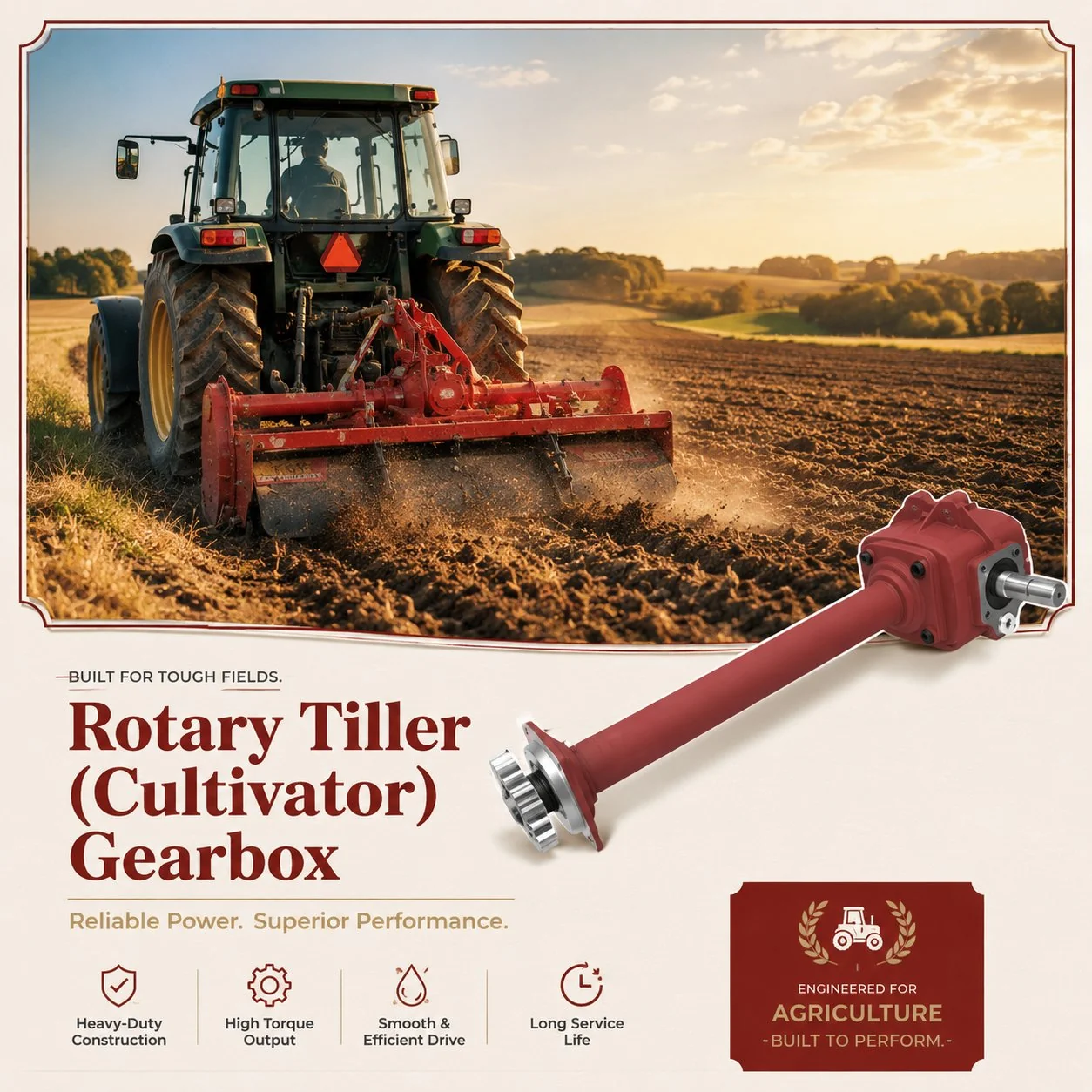
A rotary tiller gearbox — also known as a rotary cultivator gearbox or rotavator gearbox — is the right-angle PTO-driven gear unit that converts horizontal tractor PTO rotation into horizontal output rotation on a perpendicular axis, driving the blade rotor shaft through a chain or gear secondary drive. Unlike a power harrow (which uses vertical rotors with horizontal tine rotation), a rotary tiller uses L-shaped or C-shaped blades mounted on a single horizontal shaft that rotates vertically — slicing into the soil from above and throwing it backward through the rear shield to produce a fully broken, mixed seedbed in a single pass.
The rotary tiller gearbox is the most heavily loaded single-stage right-angle gearbox in the tillage category. The rotor blades are in continuous contact with the soil throughout every revolution — unlike power harrows where each rotor tine engages and then exits the soil within each rotation. This continuous soil engagement produces sustained high torque demand that increases with tillage depth, soil density, and forward speed. Stone strikes, root tangles, and compacted clay layers add intermittent impact overloads to this already high continuous baseline — making the rotary tiller gearbox one of the most demanding durability tests for any agricultural gearbox design.
How the Tiller Drive System Works
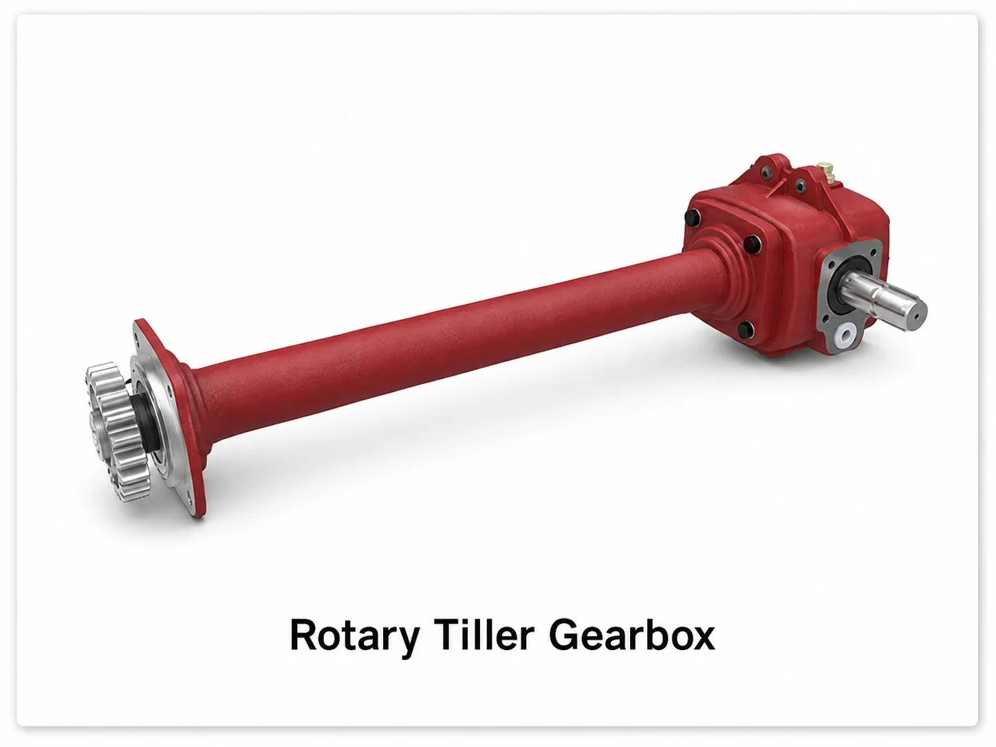
The tractor PTO drives the gearbox input shaft at 540 RPM through a driveline with slip clutch protection. Inside the gearbox, a right-angle spiral bevel gear pair redirects the power 90 degrees and applies a modest speed reduction (typically 1:1 to 1:1.5), producing a horizontal output shaft speed of 360 to 540 RPM. This output shaft carries a drive sprocket that connects to the blade rotor shaft through a heavy-duty roller chain (typically #80 or #100 pitch). The chain drive provides an additional speed reduction stage (typically 1:1.5 to 1:2), resulting in final rotor speeds of 180 to 300 RPM at the blade shaft.
The two-stage reduction architecture (bevel gearbox plus chain drive) is a deliberate design choice for the rotary tiller gearbox system. The chain acts as a mechanical fuse — if the rotor encounters a massive obstruction that exceeds the system capacity, the chain can skip or break before the more expensive bevel gears are damaged. Replacing a broken chain (a 15 to 30 minute field repair) is far less costly than replacing a cracked bevel gear pair (which requires gearbox disassembly). The chain also absorbs torsional vibration from the intermittent blade-soil engagement, reducing the shock loading transmitted back to the bevel gears.
Rotary tiller cultivator gearbox — right-angle bevel drive with chain output to rotor shaft
Rotary Tiller vs. Power Harrow: Gearbox Engineering Comparison
Gear and Bearing Design for Continuous Soil Loading
The continuous soil engagement of a rotary tiller produces a sustained high-torque baseline that the rotary tiller gearbox bearing and gear components must endure for thousands of operating hours. Unlike intermittent-engagement implements (where the gears and bearings experience periodic unloading that allows oil film recovery), the tiller gearbox bevel mesh is loaded to 70 to 100 percent of rated capacity throughout every minute of tillage operation. This sustained loading produces higher average gear tooth contact temperature, faster lubricant film degradation, and accelerated bearing fatigue compared to intermittent-duty gearboxes at the same power rating.
Case-carburised spiral bevel gears with surface hardness of 58 to 62 HRC and core hardness of 30 to 38 HRC are mandatory for the rotary tiller gearbox. The gear module is typically 5 to 7 mm — the heavy module provides tooth root strength sufficient to survive the 3 to 8 times overload torque spikes from stone strikes while maintaining adequate bending fatigue resistance under the sustained continuous loading. Tapered roller bearings at the output position handle the combined radial load from the bevel mesh and the chain tension pulling the output sprocket sideways. Bearing preload is set to 0.05 to 0.15 mm axial compression to maintain consistent gear mesh alignment throughout the full torque range — from light surface cultivation to deep, heavy clay tillage at maximum rated depth.
The roller chain connecting the gearbox output sprocket to the blade rotor shaft serves as a sacrificial overload protection element. In a severe impact event (large buried rock, steel debris, concrete fragments), the chain skips teeth or breaks before the overload torque reaches the bevel gears — protecting the most expensive component in the drive system. A replacement chain costs 20 to 50 dollars and takes 15 to 30 minutes to install; a replacement bevel gear set costs 200 to 500 dollars and requires complete gearbox disassembly. This cost asymmetry makes the chain an intentional weak link in the drive train design.
Tillage Depth, Soil Type, and Gearbox Loading
The torque demand on a rotary cultivator gearbox increases dramatically with tillage depth. Doubling the depth from 100 mm to 200 mm approximately triples the torque demand because the volume of soil engaged per revolution increases with depth squared (wider cross-section) and the soil resistance increases with depth (more compacted material at greater depth). A heavy-duty rotary tiller gearbox rated for 60 HP at 200 mm depth in medium clay may be operating at only 25 to 30 HP at 100 mm in the same soil — illustrating how depth is the dominant power variable rather than working width or forward speed.
Forward speed adds another multiplicative factor. At 2 km/h forward speed the blades take multiple cuts per metre of travel (producing fine tilth), but the power demand per metre width is moderate. At 6 km/h the blades take fewer cuts per metre (coarser tilth) but each blade bite is larger, and the total power demand increases roughly proportionally with forward speed. The rotary tiller gearbox must be rated for the maximum combination of depth plus speed that the operator intends to use — not the average operating condition. Under-rating the gearbox for the worst-case combination leads to thermal overload, accelerated gear wear, and premature bearing failure during the heaviest tillage passes.
Technical Specifications at a Glance
Blade Configuration and Gearbox Loading Patterns
The blade type fitted to the rotor shaft directly affects the torque demand on the rotary tiller gearbox. L-shaped blades (the most common type) cut into the soil on the vertical leg and then throw it backward on the horizontal leg — producing a smooth torque profile with a moderate peak as each blade enters the soil and a sustained load as it sweeps through the cutting arc. C-shaped blades (also called scimitar or sickle blades) penetrate the soil at a more aggressive angle and provide more intensive mixing — but produce higher peak torque per blade and more abrasive soil contact, increasing both gearbox loading and blade wear rate.
The number of blades per flange (typically 2, 3, or 4 blades per mounting flange, with 4 to 8 flanges across the rotor width) determines the torque pulsation frequency. A rotor with 24 blades at 240 RPM produces 5,760 blade-soil engagements per minute — a high-frequency pulsation that the gearbox bearings must endure as a continuous vibration superimposed on the sustained load. More blades per flange produce finer tilth but higher power consumption per metre of width, and the increased blade count amplifies the vibration loading on the rotary tiller gearbox bearing positions. Operators can adjust the trade-off between tilth quality and gearbox longevity by choosing the appropriate blade count for their soil type and seedbed requirements — heavier soils benefit from fewer blades at deeper cut (less pulsation per revolution), while lighter soils can use more blades for finer finish (higher pulsation but lower torque per blade).
Blade condition also affects gearbox loading. Worn, dull blades require 15 to 30 percent more torque to achieve the same tillage result as sharp blades — because dull edges compress and displace the soil rather than cutting it cleanly. This additional torque passes directly through the rotary cultivator gearbox and chain drive, accelerating wear on both components. Regular blade sharpening or replacement (every 50 to 100 operating hours in abrasive soil, 150 to 300 hours in light soil) reduces the sustained torque demand on the gearbox and extends service life.
Overload Protection: Three Lines of Defence
The rotary tiller gearbox is protected by a three-tier overload defence system. The first line is the PTO driveline slip clutch, calibrated at 1.5 to 2.0 times rated continuous torque. The second line is the individual blade bolt — each L-blade or C-blade is attached to the rotor shaft with a bolt that is designed to bend or shear if the individual blade strikes a solid obstruction, disconnecting that single blade without affecting the others. The third line is the roller chain itself, which will skip teeth or break at approximately 3 to 5 times the continuous chain tension — protecting the bevel gears from the extreme overloads that pass through the first two protection stages.
Self-resetting. Protects entire driveline. Releases at 1.5 to 2.0 times rated torque. Check calibration each season.
Sacrificial per blade. Bends or shears on individual impact. Carry 10 to 20 spares. Low-cost field replacement.
Skips or breaks at extreme overload. Protects bevel gears. Chain replacement: 15 to 30 min, 20 to 50 dollar cost.
Rotary Tiller Gearbox Oil and Lubrication
The correct rotary tiller gearbox oil is synthetic PAO EP ISO VG 320 — one grade heavier than the VG 220 used in most agricultural gearbox applications. The heavier VG 320 grade is specified because the sustained high-torque soil engagement produces elevated gear mesh contact pressures that demand thicker oil film protection. Operating temperatures during heavy tillage reach 70 to 95 degrees Celsius — similar to power harrow gearboxes and significantly higher than the 50 to 70 degrees typical of light-duty implements.
Oil change intervals are 150 to 250 hours for synthetic VG 320 and 100 to 150 hours for mineral oil — shorter than most agricultural gearbox applications due to the combination of high operating temperature, sustained heavy loading, and the soil contamination risk from the output shaft seal operating in close proximity to the soil surface. The first fill should be changed after 50 hours. Inspect the magnetic drain plug at every change — the sustained heavy loading produces more normal wear debris than light-duty gearboxes, so moderate metallic paste on the plug is expected. Coarse chips or flakes indicate abnormal gear or bearing damage requiring professional investigation.
Seasonal Maintenance Schedule
Full oil change with synthetic VG 320. Inspect chain for stretch (replace if elongation exceeds 2 percent). Check sprocket teeth for wear. Rotate output shaft by hand to verify smooth bearing action. Grease PTO driveline U-joints. Verify slip clutch calibration. Inspect blade bolts and carry spares.
Oil change mandatory. Chain tension adjustment — maintain 10 to 15 mm deflection at mid-span. Check output shaft seal for soil contamination. Inspect magnetic drain plug. Re-grease PTO driveline. Replace worn blades to maintain balanced rotor loading and reduce gearbox vibration.
Clean gearbox and chain case thoroughly — soil traps moisture during storage. Top up oil. Apply chain lubricant to prevent rust during off-season. Apply grease to exposed shaft surfaces. Store under cover. Record hours for next-season maintenance planning.
Aftermarket Rotary Tiller Gearbox Replacement
Rotary tiller gearbox replacement is among the most frequent gearbox changes in the tillage equipment aftermarket — driven by the sustained heavy loading that accelerates gear and bearing wear faster than in intermittent-duty gearboxes of equivalent power. A well-maintained tiller gearbox typically lasts 3 to 10 seasons (1,000 to 3,000 operating hours) depending on soil conditions and tillage depth. Rocky ground with frequent stone strikes accelerates gear fatigue cracking and can reduce gearbox life to 2 to 5 seasons. Cross-reference parameters include the input shaft spline profile (6-spline 1-3/8 inch is standard), the output shaft size and sprocket configuration, the mounting bolt pattern, the bevel ratio, and the chain pitch compatibility.
Our engineering team maintains cross-reference data for major rotary tiller and cultivator brands. Both complete gearbox assemblies (with matched output sprocket) and individual gear, bearing, and seal kits are available for operators who prefer to rebuild rather than replace. Contact us with your tiller model, working width, and soil conditions for accurate specification matching and gearbox selection.
Frequently Asked Questions
Till Deeper, Till Harder
From garden-scale cultivators to heavy-duty field rotavators — our rotary tiller gearboxes deliver the sustained-load durability, impact resistance, and chain-drive integration that productive soil preparation demands.
Editor: Cxm