How a Centrifugal Spreader Converts Gearbox Rotation into Precision Application
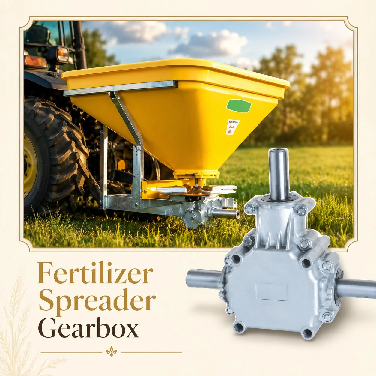
A centrifugal fertilizer spreader distributes granular material — mineral fertilizer, seed, lime, gypsum, or other granular amendments — by dropping it from a hopper onto one or two rapidly spinning discs. The spinning disc’s vanes accelerate each granule radially outward, releasing it at the disc edge with a velocity determined by the disc speed, vane geometry, and the point on the vane where the granule leaves contact. The granule then follows a ballistic trajectory through the air, landing at a distance from the spreader that depends on its release velocity, release angle, particle mass, and aerodynamic drag. The 动力输出轴变速箱 controls the disc speed — and because the throw distance is proportional to the square of the disc speed (kinetic energy = ½mv²), even a small speed error produces a disproportionate change in the spreading pattern.
Twin-disc spreaders — the dominant configuration for precision application — use two counter-rotating discs to produce a symmetric spreading pattern. The left disc throws material to the left, the right disc throws to the right, and the two patterns overlap in the centre to produce a composite distribution that is ideally trapezoidal or triangular in cross-section. Adjacent passes overlap by 50 to 70 percent of the working width, and the overlapping patterns sum to produce a uniform application rate across the full field width. This overlap-and-sum calibration principle means that even a perfectly uniform single-pass pattern still requires precise matching between left and right disc outputs — if one disc throws 10 percent farther than the other, the overlap zone shifts laterally, creating alternating over-application and under-application strips at half the working width spacing.

Twin-Disc Gearbox Architecture: Dual-Output Synchronisation
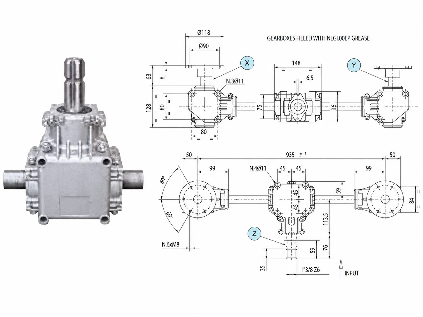
这 centrifugal spreader gearbox on a twin-disc machine is one of the most precision-demanding agricultural gearbox applications. It must convert a single horizontal PTO input into two vertical outputs — one rotating clockwise and one counterclockwise — at identical speeds. The standard architecture uses a right-angle bevel input stage (converting horizontal PTO to a transverse intermediate shaft) and a spur or helical output stage that splits the drive into two counter-rotating vertical shafts. The counter-rotation is achieved by one disc shaft meshing directly with the intermediate gear (producing one rotation direction) and the other disc shaft meshing through an idler gear (reversing the rotation direction).
Speed equality between the two disc shafts is the single most critical engineering requirement for a twin-disc spreader gearbox. A 2 percent speed difference between the left and right discs — barely detectable by feel or sound — produces a visible asymmetry in the spreading pattern that appears as crop striping after emergence. This speed equality depends on the precision of the gear manufacturing: matched tooth counts on both output gears (identical, not just similar), consistent backlash on both output meshes (set during assembly by shimming or bearing preload adjustment), and equal bearing friction on both output shafts (same bearing type, grade, and preload). Quality manufacturers like Ever-Power PTO变速箱 verify dual-output speed equality on a test stand before shipping — measuring both output speeds simultaneously under load and confirming that the differential is within 0.5 percent of nominal.
The typical gearbox ratio for a centrifugal spreader is 1:1 (540 RPM PTO produces 540 RPM disc speed) or 1:1 to 1:1.5 for wider spreading widths that require higher disc speed (700 to 810 RPM). Some precision spreaders designed for working widths of 30 to 36 metres require disc speeds of 900 to 1,200 RPM, necessitating speed-increasing ratios of 1:1.7 to 1:2.2 from a 540 RPM PTO. These higher-speed gearboxes must handle the increased centrifugal loads on the output bearings (from the spinning disc and material mass) and the elevated thermal loading from the faster gear mesh — challenges that increase with the square of the speed increase ratio.
Coefficient of Variation: How Gearbox Quality Affects Spreading Uniformity
The coefficient of variation (CV) is the industry-standard metric for spreading uniformity — defined as the standard deviation of the application rate across the working width, expressed as a percentage of the mean application rate. A CV of 10 percent means that the application rate varies by ±10 percent around the target value across the field. For high-value crops where fertilizer response is steep (winter wheat, oilseed rape, sugar beet), every percentage point of CV above the optimal level translates directly into yield loss: over-applied areas suffer from lodging, nutrient imbalance, or environmental runoff, while under-applied areas fail to reach their yield potential.
The gearbox contributes to CV through two mechanisms. First, absolute speed accuracy determines whether the disc speed matches the speed assumed in the spreader calibration — if the gearbox ratio is 0.5 percent off nominal (producing 537 RPM instead of 540), the throw distance shifts by approximately 1 percent, which compounds across the full spreading width to produce a pattern that is slightly narrower or wider than intended. This absolute error is fixed and consistent — it shifts the entire pattern uniformly and is correctable through recalibration. Second, speed fluctuation (cyclic variation in output speed caused by gear mesh excitation, bearing irregularities, or PTO driveline pulsation) produces dynamic pattern instability — the throw distance varies slightly with each disc revolution, creating a random scatter overlay on the intended pattern that cannot be calibrated away and directly adds to the CV measurement.
For precision spreading with CV targets below 10 percent, the gearbox should contribute less than 1 percent speed fluctuation — meaning the output speed varies by no more than ±5 RPM around a 540 RPM nominal. Achieving this stability requires AGMA Quality 10 or better gear tooth accuracy, properly preloaded bearings with minimal radial play, and a PTO driveline in good condition (no worn U-joints that inject cyclic speed variation at the gearbox input). For a broader understanding of spreader gearbox configurations across different spreading applications, see our engineering guide on 肥料撒布机变速箱 design and selection.
Variable-Rate Application: Gearbox Integration with Precision Agriculture
Modern precision spreaders adjust the application rate in real time based on GPS prescription maps — applying more fertilizer in high-yield zones and less in low-yield zones to optimise nutrient use efficiency and minimise environmental impact. This variable-rate capability requires the ability to change the material flow rate (controlled by the hopper gate opening) and, on advanced systems, the disc speed (to maintain optimal pattern shape as the flow rate changes) while the spreader moves through the field.
Three disc speed control strategies are used in variable-rate spreaders. The simplest maintains fixed disc speed from the 动力输出轴变速箱 and adjusts only the flow gate — this changes the application rate but does not adjust the spreading pattern for the changed flow, producing slight pattern distortion at rates significantly different from the calibration rate. The second strategy uses a hydraulic motor to supplement or replace the mechanical disc drive, providing infinitely variable disc speed independent of PTO speed — this produces the most precise pattern control but adds cost, complexity, and hydraulic system dependency. The third strategy uses electronic PTO speed control (available on some modern tractors) to vary the PTO speed and therefore the gearbox output speed in response to the prescription map controller — this provides variable disc speed through the existing mechanical gearbox without adding hydraulic components, but it also changes the speed of every other PTO-driven function on the machine (which may not be acceptable if the spreader shares PTO drive with an agitator or other speed-sensitive component).
Corrosion Protection: Fertiliser Dust, Lime, and Moisture
Centrifugal spreader gearboxes operate in a corrosive dust cloud generated by the spinning discs — fine fertiliser particles, lime dust, and hygroscopic salt crystals that settle on every exposed surface and penetrate into every unsealed gap in the housing and shaft seal assemblies. Ammonium nitrate fertiliser is particularly aggressive: it absorbs atmospheric moisture to form a corrosive solution that attacks bare cast iron, degrades standard paint, and crystallises inside any unsealed crevice, creating expanding salt deposits that can force housing joints apart over time. Urea fertiliser has similar hygroscopic properties, and lime (calcium carbonate) generates fine abrasive dust that infiltrates shaft seals and accelerates wear on every moving surface it contacts.
The gearbox housing requires minimum epoxy powder coating for fertiliser spreader service — standard acrylic or alkyd paint deteriorates within one to two seasons under the combined attack of fertiliser chemicals, moisture, and UV exposure. The disc mounting flanges and exposed shaft surfaces that contact fertiliser directly should be stainless steel or hard-chrome plated to resist the corrosive and abrasive environment. Shaft seals must exclude the fine dust particles generated during spreading while resisting the chemical environment — double-lip seals with a grease-purged chamber are the minimum specification, with FKM (Viton) lip material for spreaders used with ammonium-based fertilisers. Sealed breather valves prevent the hygroscopic fertiliser dust from being drawn into the gearbox housing during the thermal breathing cycle that occurs as the gearbox cools after each spreading session.
Post-operation cleaning is essential for 农业齿轮箱 longevity on fertiliser spreaders. Washing the spreader immediately after each use — including the gearbox housing exterior, disc mounting surfaces, and all exposed fasteners — removes the hygroscopic fertiliser residue before it absorbs moisture and begins its corrosive attack. A spreader left unwashed overnight in humid conditions can develop visible corrosion on unprotected steel surfaces by morning. For lime spreading, cleaning is even more critical because lime dust mixed with moisture forms calcium hydroxide — a moderately alkaline paste (pH 12+) that attacks aluminium components and accelerates corrosion of zinc-plated fasteners.
Maintenance and Calibration for Spreader Gearboxes
The oil change interval for a centrifugal spreader gearbox is typically 300 to 500 hours — the moderate duty cycle (spreaders operate fewer total hours per season than irrigation pumps or harvest equipment, but in a corrosive and abrasive dust environment that degrades oil additives faster than clean-air applications) requires a balance between hour-based and condition-based maintenance. Check the oil colour and consistency at least twice per season: clean amber indicates satisfactory condition; darkening suggests thermal degradation; milky appearance indicates moisture entry (common on spreaders that are washed frequently); and gritty texture indicates particulate contamination from seal failure. Replace oil immediately whenever contamination is detected rather than waiting for the hour-based interval.
Disc speed calibration should be verified at the start of each spreading season using a handheld optical tachometer on each disc shaft. Compare the measured speed to the nominal gearbox output speed (PTO speed × gearbox ratio) — any deviation greater than 2 percent indicates either a PTO speed error (check tractor RPM at rated PTO speed), gearbox ratio error (unlikely unless the gearbox has been replaced with a non-original unit), or measurement error. On twin-disc gearboxes, the critical check is the speed difference between the two discs: measure both simultaneously at the same PTO speed and verify that the differential is less than 1 percent of nominal. A differential exceeding 1 percent produces visible pattern asymmetry that degrades the composite CV after overlap.
动力输出轴 condition directly affects disc speed stability. A worn U-joint introduces cyclic speed variation at twice the PTO rotation frequency — a pulsation that the gearbox transmits directly to both discs, creating a rhythmic variation in throw distance that degrades the CV by 2 to 5 percentage points depending on the severity of the U-joint wear. Inspect and grease the PTO driveline U-joints before each spreading season, and replace any joint showing detectable bearing play. For precision spreading with CV targets below 8 percent, the PTO driveline is as important to pattern quality as the spreader calibration itself.
常见问题解答
Precision Spreading Starts Here
From single-disc broadcasters to twin-disc precision spreaders — our gearboxes are factory-verified for speed accuracy and dual-output equality that directly translates into lower CV and more uniform crop nutrition. Fertiliser-rated corrosion protection packages available on every model.
编辑:Cxm