What Is a PTO Speed Increase Gearbox?
A PTO speed increase gearbox — also called a speed increaser, overdrive gearbox, or step-up gearbox — is a gear unit mounted between the tractor PTO output and the implement driveline that increases the rotational speed while proportionally reducing the torque. The most common application is converting a standard 540 RPM PTO to 1,000 RPM to power implements designed for the higher-speed PTO standard — enabling older or smaller tractors with only 540 RPM PTO capability to operate modern 1,000 RPM equipment without engine or transmission modification.
Beyond the 540-to-1,000 conversion, PTO speed increase gearbox units serve a wide range of agricultural speed increaser applications: driving centrifugal spray pumps at 3,000 to 4,000 RPM, powering PTO generators at the precise speed needed for 50 or 60 Hz electrical output, spinning fertilizer spreader discs at 700 to 1,000 RPM, and running finish mower blades at the high tip speed needed for clean cutting. In each case, the gearbox converts the fixed tractor PTO speed into the specific higher speed that the implement requires — adding speed versatility to a tractor without altering the engine or PTO mechanicals.
How Speed Increase Works: Torque-Speed Trade-Off
Every PTO speed increase gearbox operates on the fundamental torque-speed trade-off: when speed goes up, torque goes down by the same ratio (minus efficiency losses). A 1:1.85 PTO gearbox receiving 540 RPM at 795 Nm (60 HP) delivers 1,000 RPM at only 408 Nm (accounting for 95 percent efficiency) — roughly half the input torque. This torque reduction means the implement must be designed for the lower torque at higher speed — which is inherently the case for equipment specified for 1,000 RPM operation, where the design assumes the lower torque that accompanies the higher speed.
The PTO speed increase gearbox ratio is chosen to produce the exact output speed the implement requires. For the standard 540-to-1,000 RPM conversion, the ratio is 1:1.85. For driving a centrifugal spray pump at 3,240 RPM from 540 PTO, the ratio is 1:6. For a PTO generator producing 60 Hz electricity (requiring 1,800 RPM synchronous speed), the ratio is 1:3.33. Each application demands its own precisely calculated ratio — using an incorrect ratio produces the wrong implement speed, with consequences ranging from reduced performance (mower cutting too slowly) to mechanical destruction (pump or generator over-speeding beyond design limits).
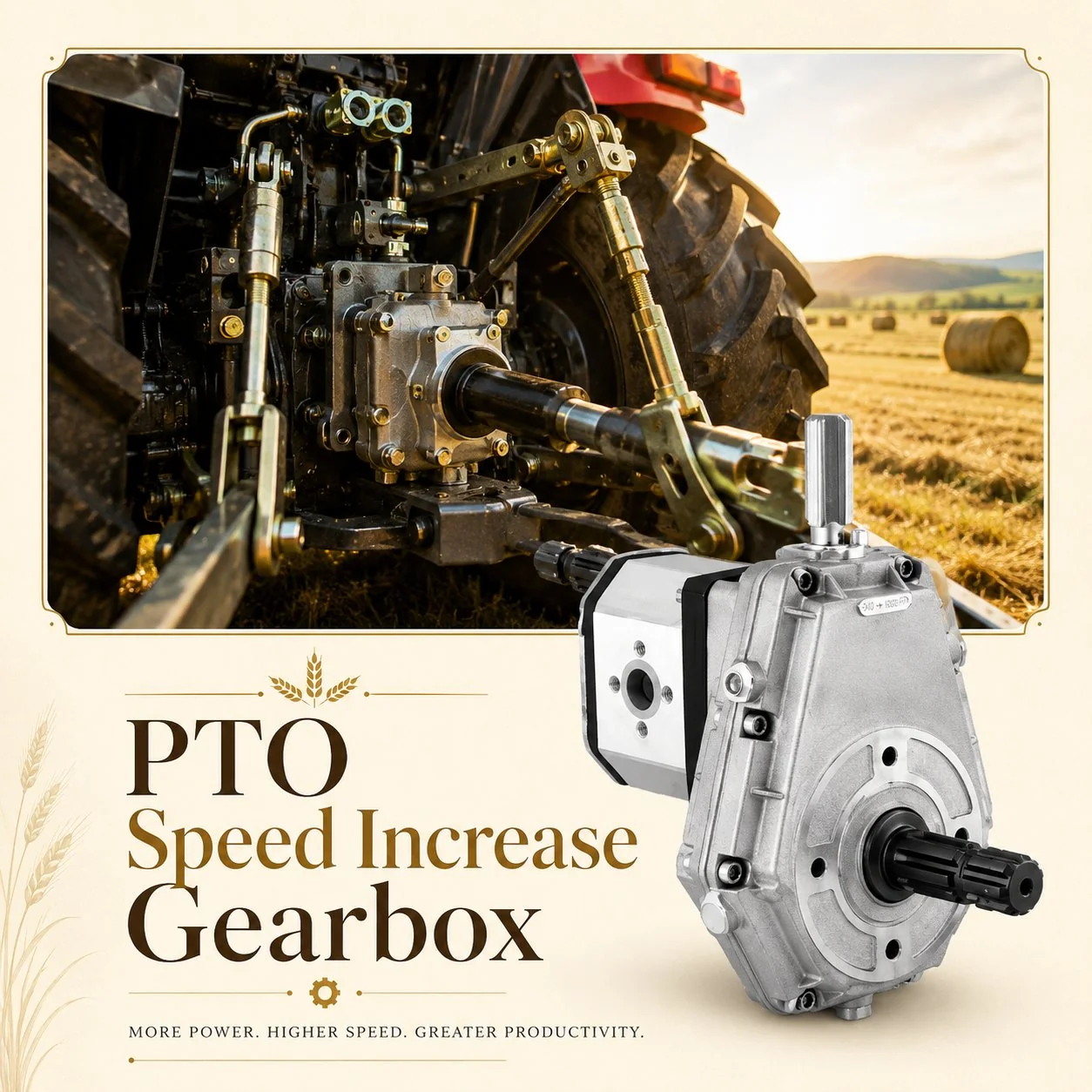
PTO speed increase gearbox — step-up ratio for high-RPM implement drive
A PTO speed increase gearbox with the wrong ratio can over-speed an implement beyond its mechanical design limit — causing centrifugal bearing failure in pumps, rotor disintegration in generators, or blade throw in mowers. Always verify that the gearbox output speed at rated PTO RPM matches the implement rated input speed. If the tractor PTO produces 540 RPM and the implement requires 1,000 RPM, the correct ratio is 1:1.85 — not 1:2 (which would produce 1,080 RPM, an 8 percent overspeed that exceeds most implement safety margins).
Common Applications and Required Ratios
Inline vs. Right-Angle Speed Increasers
A PTO speed increase gearbox is available in two fundamental architectures. An inline speed increaser mounts directly on the tractor PTO stub and drives the implement driveline along the same horizontal axis — using helical or spur gear pairs to achieve the speed multiplication. Inline units are compact and maintain the driveline alignment between tractor and implement, but are limited to moderate ratios (typically 1:1.5 to 1:2) because higher ratios require more gear stages and produce a longer, heavier unit that overhangs the PTO stub and stresses the tractor PTO bearings.
A right-angle speed increaser uses spiral bevel gears to redirect the power axis by 90 degrees while simultaneously increasing the speed. This architecture is used when the implement needs vertical output (mower blade spindles, spreader discs) or when higher ratios are required (1:3 to 1:6 for pumps and generators). Right-angle units are typically mounted on the implement rather than on the tractor PTO stub — distributing the weight to the implement frame rather than cantilevering it from the PTO bearing. For implements requiring both a direction change and a speed increase, the right-angle PTO gearbox achieves both functions in a single compact unit rather than requiring a separate direction-change gearbox plus an inline speed increaser.
The PTO speed increaser 540 to 1000 conversion — the most commonly purchased speed increase gearbox in the agricultural market — is available in both architectures. The inline version is preferred when it simply mounts between the tractor PTO and a standard implement driveshaft (maintaining the original driveline geometry). The right-angle version is chosen when the implement already incorporates a right-angle drive (mowers, spreaders) and the speed increase can be integrated into the existing gearbox rather than added as a separate unit.
For the standard 540-to-1,000 conversion at power levels above 50 HP, the PTO overdrive gearbox must be robustly supported — either with a separate mounting bracket attached to the tractor drawbar or lower links, or through the implement frame. Cantilevering a heavy gearbox (15 to 30 kg) from the tractor PTO stub at 1,000 RPM output generates bearing loads and vibration that can damage both the gearbox output bearing and the tractor PTO stub bearing if the support is inadequate.

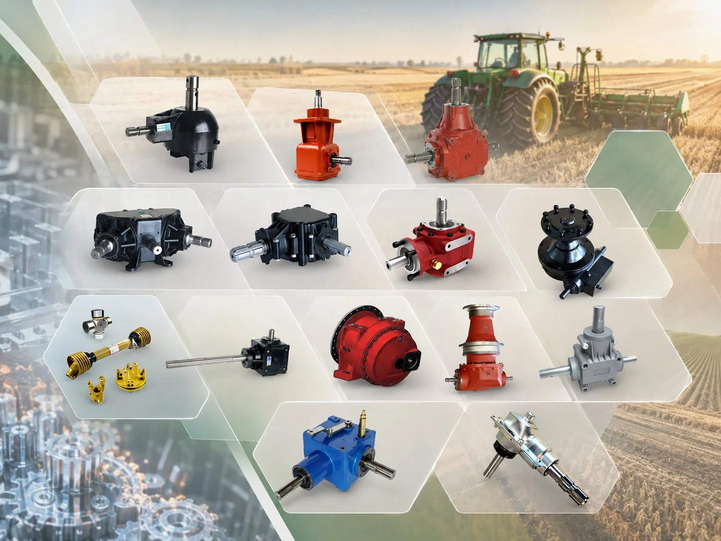
Right-angle PTO speed increase gearbox — bevel-gear overdrive for vertical-output implements
High-Speed Bearing Design and Thermal Management
The output shaft of a PTO speed increase gearbox runs at 1,000 to 3,000+ RPM — significantly faster than the 150 to 540 RPM output of most agricultural gearboxes. This sustained high-speed operation places the dominant engineering demand on the PTO overdrive gearbox bearing at the output position: bearing L10 life is inversely proportional to speed, so doubling the output speed halves the theoretical bearing life at the same load. Deep-groove ball bearings with C3 internal clearance (allowing for thermal expansion at operating temperature) and high-speed-rated synthetic grease fill are the standard choice for output positions running above 1,000 RPM. Angular contact bearings may be specified when axial thrust from the driven implement (pumps, mower blades) adds to the radial gear mesh loads.
Heat generation increases with the square of the speed at the gear mesh and bearing positions. A 1:1.85 speed increaser running at 60 HP continuous produces approximately 1.8 to 3.0 kW of waste heat (at 95 to 97 percent efficiency) — a modest amount, but concentrated in a compact housing that may have only 0.2 to 0.5 square metres of external surface area for heat dissipation. If the housing reaches sustained temperatures above 90 degrees Celsius, oil degradation accelerates and bearing grease life decreases sharply. Synthetic PAO-based EP gear oil (ISO VG 220) provides superior thermal stability and oxidation resistance compared to mineral oil at these elevated temperatures — maintaining its protective properties for 300 to 500 hours at temperatures that would degrade mineral oil within 100 to 150 hours.
Housing temperature 60 to 80 degrees Celsius. Mineral or synthetic VG 220 adequate. Standard cast iron housing provides sufficient heat dissipation. Oil change: 300 to 500 hours.
Housing temperature 80 to 100+ degrees Celsius. Synthetic PAO VG 220 mandatory. Finned housing or auxiliary oil cooler may be needed. Oil change: 200 to 300 hours. Monitor temperature routinely.
Technical Specifications at a Glance
PTO Driveline Integration and Safety
An inline PTO speed increase gearbox mounts directly on the tractor PTO stub — adding 150 to 300 mm of length and 8 to 30 kg of weight to the PTO overhang. The PTO driveline connecting the gearbox output to the implement must be rated for the higher output speed and the reduced torque — not the input speed and torque. A driveline rated for 540 RPM at 795 Nm (60 HP) may not be rated for 1,000 RPM at 408 Nm even though the power is the same: U-joint bearing speed ratings are independent of torque, and exceeding the bearing speed limit causes premature joint failure regardless of the torque level.
Safety shielding is particularly important for speed increaser installations because the exposed rotating components between the tractor PTO and the gearbox input — and between the gearbox output and the implement driveline — rotate at different speeds. The PTO stub guard must cover the input shaft at 540 RPM, and the output driveline guard must be rated for the higher output speed. Entanglement hazards are most severe at the speed-change point where an operator may not realise that the exposed shaft on one side of the gearbox rotates nearly twice as fast as the shaft on the other side.
PTO Speed Increase Gearbox Oil and Lubrication
The correct PTO speed increase gearbox oil is synthetic PAO EP ISO VG 220 for all applications above 30 HP or above 1,500 RPM output. The higher gear mesh speed generates elevated contact temperatures that degrade mineral oil faster than in equivalent speed-reducing agricultural gearbox applications. For light-duty applications (below 30 HP, below 1,500 RPM output), mineral SAE 80W-90 (ISO VG 220 equivalent) is acceptable but offers no cost advantage given the small oil volume (0.5 to 2.0 litres) and the extended change interval that synthetic provides.
Oil change intervals are 200 to 500 hours depending on power level and operating temperature. The first fill should be changed after 50 hours to remove break-in particles from the high-speed gear mesh. Inspect the magnetic drain plug at every change — metallic particles indicate developing gear wear or bearing fatigue. For sustained high-power applications (above 75 HP, output above 1,000 RPM), oil temperature monitoring is recommended: if the housing surface temperature exceeds 90 degrees Celsius (too hot to touch for more than one second), investigate the cause — possible issues include low oil level, incorrect viscosity grade, excessive load beyond the gearbox rating, or bearing deterioration generating abnormal friction heat.
Speed Reduction: The Reverse Application
While the primary market for PTO speed change gearboxes is the speed-increase direction (540 to 1,000 RPM), an equally important but less visible market exists for speed reduction — converting a 1,000 RPM PTO to 540 RPM for operating older implements designed for the lower-speed standard. Many modern high-horsepower tractors (above 100 HP) are equipped with 1,000 RPM PTO as standard, but farms often retain older 540 RPM implements (rotary mowers, hay tedders, manure spreaders) that represent significant capital investment and still have years of useful life remaining. A 1.85:1 speed-reducing PTO speed increase gearbox (simply the same unit installed in the reverse direction) converts the 1,000 RPM tractor output to 540 RPM for these legacy implements — extending the useful life of existing equipment rather than requiring premature replacement.
The engineering considerations for speed reduction are the mirror image of speed increase: the output shaft runs slower (lower bearing fatigue cycling) but carries higher torque (increased gear tooth stress). The torque multiplication at 1.85:1 reduction means the output shaft and bearings must handle 1.85 times the input torque — a significant increase that must be verified against the gearbox continuous torque rating. Never exceed the rated continuous torque by operating a speed reducer on a tractor with more HP than the gearbox is rated for — the higher torque will accelerate gear and bearing wear even though the speed is well within limits.
Maintenance Schedule
Verify gearbox ratio matches implement requirement. Fill with correct oil grade and volume. Check input/output shaft alignment and coupling security. Verify driveline speed rating for output RPM. Inspect all safety shields for completeness and condition.
Oil change with fresh synthetic VG 220. Inspect magnetic drain plug for wear particles. Check output bearing for noise or temperature increase. Verify mounting bracket integrity (inline units stress the PTO stub mounting). Grease PTO driveline U-joints.
Top up oil to maximum level. Apply grease to exposed shaft surfaces. Store the gearbox (or the implement with gearbox attached) under cover. Record operating hours for next-season oil change planning.
Aftermarket PTO Speed Increase Gearbox Replacement
PTO speed increase gearbox replacement is driven primarily by output bearing fatigue from sustained high-speed operation. A well-maintained speed increaser typically lasts 3,000 to 8,000 operating hours (5 to 15 years depending on annual use). Cross-reference parameters include the input spline profile (6-spline or 21-spline), the output shaft configuration (shaft size, spline, or coupling type), the speed ratio, the power rating, and the mounting arrangement (inline PTO stub mount vs. implement bracket mount). An incorrect ratio even by a small margin (1:1.85 vs. 1:2, for example) can over-speed the implement — always verify the exact ratio before ordering a replacement.
Our engineering team maintains cross-reference data for major speed increaser brands and can supply aftermarket replacements with verified ratio, power, and dimensional accuracy. Both inline and right-angle configurations are available across the full ratio range (1:1.5 to 1:6). Contact our team with your current gearbox part number, or your tractor PTO speed and implement speed requirement, for precise specification matching.
Frequently Asked Questions
Unlock Every Implement with One Gearbox
From the standard 540-to-1,000 conversion to high-ratio pump and generator drives — our PTO speed increase gearboxes deliver precise output speed, thermal reliability, and multi-season bearing life for every high-RPM application.
Editor: Cxm