How a Power Harrow Gearbox Distributes Power
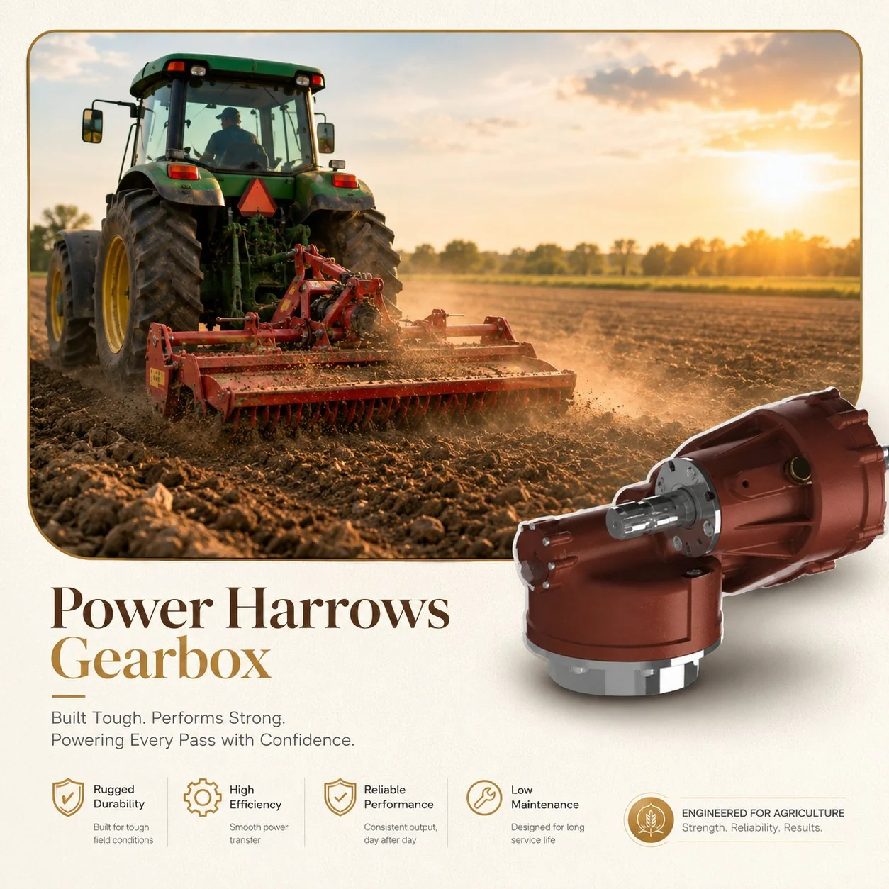
A power harrow is fundamentally different from every other PTO-driven soil tillage implement because its tines rotate on vertical axes rather than horizontal ones. Instead of slicing horizontally through soil like a rotary tiller, each pair of tines spins vertically — penetrating downward, sweeping laterally through the soil, and lifting back up in a circular path that shatters clods and mixes the topsoil without burying crop residue or creating a compacted pan layer below the working depth.
The gearbox that drives this action is among the most complex in agricultural machinery. A typical 3-meter working width power harrow has 10 to 12 individual rotor shafts, each carrying two tines. Every rotor must spin at the same speed — typically 250 to 350 RPM — and adjacent rotors must turn in opposite directions so that their overlapping tine paths interleave rather than collide. The power harrow gearbox accomplishes this through a central input shaft driving a series of bevel or spur gear pairs, with idler gears between each rotor pair to reverse the rotation direction of every second shaft.
The input power arrives from the tractor PTO — usually at 1,000 RPM for harrows above 2.5 meters working width — and enters a primary reduction gearbox that reduces speed from 1,000 RPM to approximately 300 RPM before distributing torque laterally across the full working width. This primary gearbox is typically a bevel gear pair (1,000 RPM input to a horizontal cross-shaft) followed by spur gear distribution along the cross-shaft to each individual rotor. The total power demand is substantial: a 3-meter power harrow operating at 8 cm depth in medium-textured soil requires 80 to 120 HP at the PTO shaft, with peak torque spikes 2 to 3 times higher when the tines strike stones or compacted clay zones.
Typical Power Demand per Meter of Working Width
25–40 HP/m
At 8 cm working depth in medium soil · 1,000 RPM PTO · 6–8 km/h forward speed
A 4-meter power harrow may demand 100–160 HP continuously through its gearbox
Multi-Rotor Synchronization Through Idler Gears
The defining engineering challenge of a power harrow gearbox is synchronizing 10, 12, or even 16 individual rotors across a working width of 2.5 to 6 meters while maintaining counter-rotation between adjacent pairs. The synchronization method determines gearbox cost, complexity, maintenance requirements, and — critically — what happens when a single tine strikes a large stone.
Most modern power harrows use a gear train architecture where each rotor shaft carries a spur gear at its upper end, and these gears mesh directly with their neighbors through a series of idler gears mounted on the gearbox housing. Because each idler reverses the rotation direction, the net effect is that rotor 1 turns clockwise, rotor 2 counterclockwise, rotor 3 clockwise, and so on across the full width. The gear train is enclosed in a sealed oil bath housing that runs along the top of the harrow frame.
This continuous gear train provides rigid mechanical synchronization — every rotor is locked to every other rotor through the gear mesh, ensuring perfectly matched speed regardless of individual soil resistance variations. The disadvantage of rigid coupling is that a sudden impact on one rotor (from a buried stone, for example) transmits a shock pulse through the entire gear train. Without adequate overload protection, that pulse can damage gears far from the impact point. Two protection strategies address this: individual shear pins at each rotor mounting that fail before the shock reaches damaging levels, and a central slip clutch on the PTO driveline that limits the total torque entering the gearbox to a safe maximum.
An alternative architecture used on some lighter-duty power harrows replaces the continuous spur gear train with individual bevel gear drives from the cross-shaft to each rotor. This eliminates the inter-rotor gear mesh, so a stone impact on one rotor does not propagate to its neighbors. However, it also means each rotor is individually loaded from the cross-shaft, which requires more robust bearings at each bevel mesh point and results in a heavier, more expensive gearbox housing. For harrows above 3 meters working width, the continuous spur gear train with shear pin protection remains the dominant design.
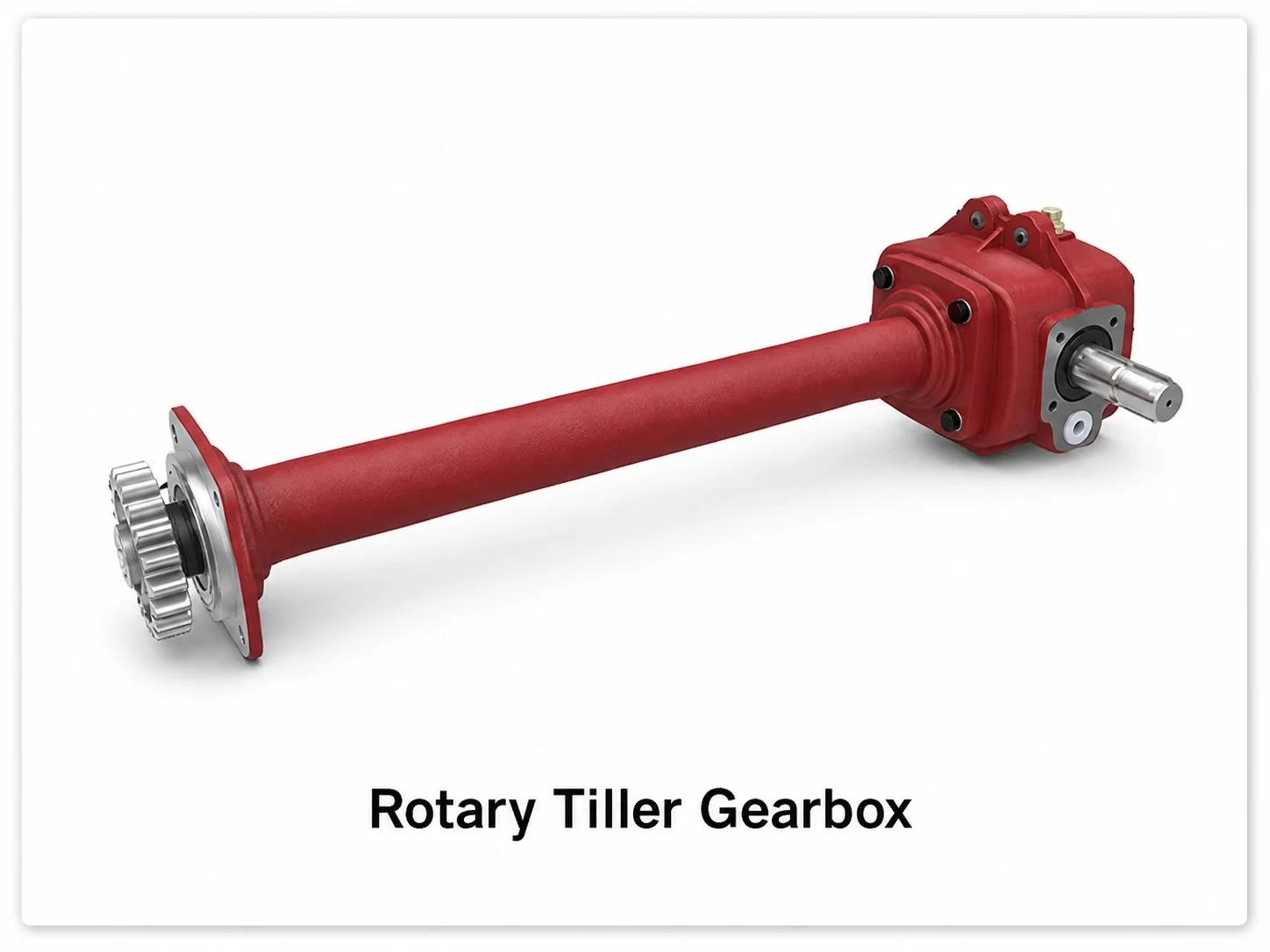
The gear engineering principles in rotary tiller and power harrow gearboxes share common foundations in bevel gear power transmission
Power Harrow vs. Rotary Tiller: A Gearbox Engineering Comparison
Operators frequently compare power harrows and rotary tillers for seedbed preparation, but from a gearbox design perspective, the two implements solve fundamentally different mechanical problems. Understanding these differences explains why the gearboxes are not interchangeable, why power harrow gearboxes cost significantly more, and why each design excels in its intended application. For a detailed analysis of rotary tiller gearbox design and selection criteria, see our companion article on tiller gearbox engineering.
| Parameter | Power Harrow Gearbox | Rotary Tiller Gearbox |
|---|---|---|
| Tine axis | Vertical | Horizontal |
| Tine speed | 250–350 RPM | 180–280 RPM |
| Number of driven shafts | 10–16 (individually geared) | 1 (single rotor shaft) |
| Gear type | Bevel input + spur train with idlers | Bevel input + chain or direct drive |
| Gear count | 20–35 gears | 2–4 gears |
| Power per meter width | 25–40 HP/m | 12–25 HP/m |
| Oil volume | 8–20 liters (long housing) | 1.5–4 liters (compact housing) |
| Stone protection | Individual rotor shear pins + PTO clutch | PTO shear bolt only |
| Soil profile after pass | Crumbled, no inversion, no pan | Mixed/inverted, possible hardpan |
| Typical gearbox cost | 2–5× higher than equivalent tiller | Lower (simpler architecture) |
The cost difference is directly attributable to gearbox complexity. A rotary tiller gearbox drives a single horizontal shaft through one bevel gear pair — two or four gears total. A power harrow gearbox drives 10 to 16 individual vertical shafts through a continuous gear train containing 20 to 35 precision-machined spur gears, each requiring its own bearing, seal, and mounting bore machined into a housing that spans the full working width. The housing alone weighs 50 to 100 kg on a 3-meter harrow and must maintain bore alignment across its entire length to prevent binding in the gear train.
Stone Impact Protection: Saving the Gear Train
Power harrows are used extensively in stony soils — particularly in Northern Europe, parts of Australia, and mountainous Asian agricultural regions — where buried rocks represent a constant threat to the gearbox. A tine striking a 10 kg stone at 300 RPM generates an instantaneous torque spike that can exceed 5 times the normal operating torque. Without protection, that spike propagates through the gear train and can crack spur gear teeth three or four rotors away from the impact point.
Three-Level Protection Hierarchy in Power Harrow Gearboxes:
Rotor Shear Pin (First Line of Defense)
Each individual rotor shaft connects to its driving gear through a shear pin — a precisely calibrated hardened steel pin that breaks at a specific torque threshold (typically 150–200% of normal operating torque). When a tine hits a stone, the shear pin on that specific rotor breaks, disconnecting it from the gear train within milliseconds. The remaining rotors continue operating normally. Field replacement takes 2 to 5 minutes per pin. Carry a minimum of 10 spare pins per operating shift.
PTO Driveline Slip Clutch (System-Level Protection)
If the shear pin does not break fast enough — or if multiple rotors strike a large buried object simultaneously — the PTO shaft slip clutch engages, limiting total input torque to the gearbox. This protects the primary bevel gear set and the cross-shaft bearings from overload. Slip clutch settings should be calibrated to 120–130% of the harrow’s maximum rated PTO torque at working RPM.
Gear Tooth Root Strength Margin (Inherent Safety)
A well-designed power harrow gearbox includes a minimum 2× safety factor on gear tooth bending stress — meaning the gear teeth can withstand twice the normal operating load before risking fatigue failure. This inherent margin absorbs the moderate impact transients that occur continuously during normal operation in stony ground without relying on the shear pins for every event.
Operators who remove or bypass shear pins to avoid frequent replacement stops in very stony fields are making a dangerous economic calculation. Without the shear pin acting as a sacrificial fuse, every stone impact transmits its full shock energy into the gear train. Over a season, cumulative minor impacts cause gear tooth micro-fatigue that eventually leads to catastrophic gear failure — typically at the worst possible time during peak planting season. The cost of 50 shear pins across a season is a fraction of one gearbox rebuild.
Lubrication and Thermal Management in Power Harrow Gearboxes
The long, narrow housing of a power harrow gearbox creates a unique lubrication challenge. Oil must reach gear meshes and bearings distributed across 2.5 to 6 meters of horizontal length while the harrow operates at varying ground slopes. At one end of a hillside pass, the oil pools at the low side of the housing, potentially leaving the high-side gears and bearings oil-starved. Quality power harrow gearbox designs address this through oil distribution channels machined into the housing interior, oil splash plates that redirect lubricant from the rotating gears toward distant bearings, and sight glasses at both ends of the housing so the operator can verify oil level from either side.
Oil volume in a power harrow gearbox is typically 8 to 20 liters — significantly more than the 1.5 to 4 liters in a rotary tiller gearbox — because the long housing must maintain sufficient oil depth across its entire length to submerge the lowest gear mesh even on sloped ground. Overfilling causes churning losses that waste power and generate unnecessary heat; underfilling risks bearing starvation on hillside passes. Follow the manufacturer’s specified fill level precisely, and check both end sight glasses before each operating day.
Thermal load is substantial in power harrow gearboxes because of the high number of gear meshes operating simultaneously. Each spur gear mesh dissipates 1–2% of the transmitted power as heat. With 15 to 30 active gear meshes in the train, total heat generation can reach 5–8% of input power — 4 to 13 kW of continuous heat at 80 to 160 HP input. The long, flat housing provides a large surface area for heat dissipation, but in hot climates or during continuous heavy-duty operation, internal oil temperatures can exceed 90 °C. EP 80W-90 or 85W-140 gear oil rated for GL-5 service handles these temperatures adequately in most conditions; synthetic alternatives extend thermal safety margin in extreme applications.
Power Harrow Gearbox Selection Guide
Selecting the correct power harrow gearbox — whether for a new implement build or as a replacement on an existing harrow — requires matching four critical parameters to your tractor and soil conditions. Errors in any of these specifications lead to premature failure, excessive fuel consumption, or inadequate soil preparation quality.
| Parameter | Compact (2–2.5 m) | Standard (3–4 m) | Heavy-Duty (4.5–6 m) |
|---|---|---|---|
| Tractor HP required | 50–80 HP | 80–160 HP | 160–350+ HP |
| PTO input speed | 540 RPM | 1,000 RPM | 1,000 RPM |
| Rotor count | 6–8 | 10–14 | 16–22 |
| Gear train type | Individual bevel drives | Continuous spur gear train | Continuous spur + reinforced idlers |
| Oil volume | 4–8 liters | 10–14 liters | 15–20+ liters |
| Application | Vineyard, orchard, specialty crops | Broadacre cereals, vegetables | Large-scale grain, sugar beet |
For replacement gearbox sourcing, the most critical measurement is the mounting bolt pattern and housing dimensions — power harrow gearbox housings are implement-specific, and even a 5 mm mismatch in bolt spacing makes a unit incompatible. Supply your agricultural gearbox supplier with the original gearbox part number, harrow brand and model, working width, rotor count, and PTO input speed. A responsible supplier like Ever-Power PTO Gearbox will verify all dimensions and confirm gear ratio compatibility before manufacturing or shipping.
Maintenance Priorities for Maximum Gear Train Life
The multi-gear architecture of a power harrow gearbox means that wear on any single gear affects the entire train’s performance. A worn idler gear introduces backlash that increases impact loading on its neighboring gears, accelerating their wear in a cascade effect. Proactive maintenance stops this cascade before it begins.
Check and maintain oil level before every operating day — this is the single highest-return maintenance action for any PTO gearbox application, but it is especially critical in power harrows because the long housing amplifies the consequences of low oil level. Drain and replace the gear oil every 200 operating hours or annually, whichever comes first. During oil changes, inspect the drained oil for metallic particles using a magnet — iron particles indicate gear tooth wear, while bronze particles suggest bearing cage wear. Either finding warrants a closer inspection of the gear train internals before the next operating season.
Inspect shear pins at the start of each operating day and after any noticeable impact event. Replace any pin that shows bending, cracking, or deformation — even if it has not fully sheared. A deformed pin has absorbed part of its energy capacity and will fail at a lower torque threshold than a new pin, providing inconsistent protection. Always use the manufacturer’s specified shear pin grade and hardness; field-fabricated pins from random bolt stock provide unpredictable shear strength.
Frequently Asked Questions
Get a Custom Agricultural Gearbox Quote
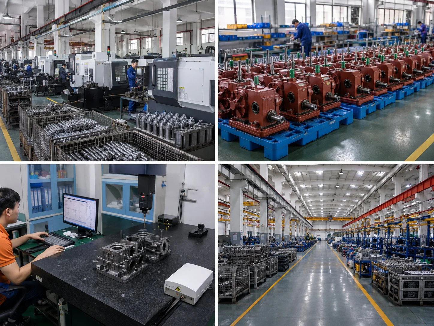
From compact vineyard harrows to heavy-duty broadacre units, our PTO gearbox engineering team delivers precision-manufactured power harrow gearboxes with verified dimensional compatibility, load-tested gears, and worldwide shipping — backed by 20+ years of agricultural gearbox manufacturing expertise.
Editor: Cxm