How a Spading Machine Works: Crankshaft-Driven Soil Inversion
A reciprocating spading machine uses sets of flat spade blades mounted on a crankshaft mechanism — each blade enters the soil vertically to a depth of 200 to 400 mm, lifts a discrete clod weighing 5 to 15 kg, rotates it through 180 degrees as the crankshaft turns, and deposits the inverted clod back into the tillage slot. The blades are arranged in staggered rows across the working width (typically 2 to 4 rows of 4 to 8 spades each, totalling 8 to 32 individual spade blades), with each row timed to enter the soil at a different phase of the crankshaft revolution — distributing the combined lifting load across the crankshaft rotation and reducing the peak torque variation that the caja de engranajes de la toma de fuerza must absorb.
The crankshaft operates at 100 to 250 RPM — far slower than a rotary tiller rotor (200 to 280 RPM) and orders of magnitude slower than a speed-increasing gearbox output. From a 540 RPM PTO, this requires a 1:2.2 to 1:5.4 speed reduction — placing the spading machine gearbox firmly in the high-torque reducer category alongside deep cultivator gearboxes and TMR mixer gearboxes. The combined total lifting force across a typical 2-metre working width ranges from 5,000 to 20,000 N depending on soil type, soil moisture, and working depth — a sustained and demanding mechanical requirement that requires heavy-duty gears, oversized shaft diameters, and robust bearing arrangements optimised for continuous cyclic loading at low rotational speed.
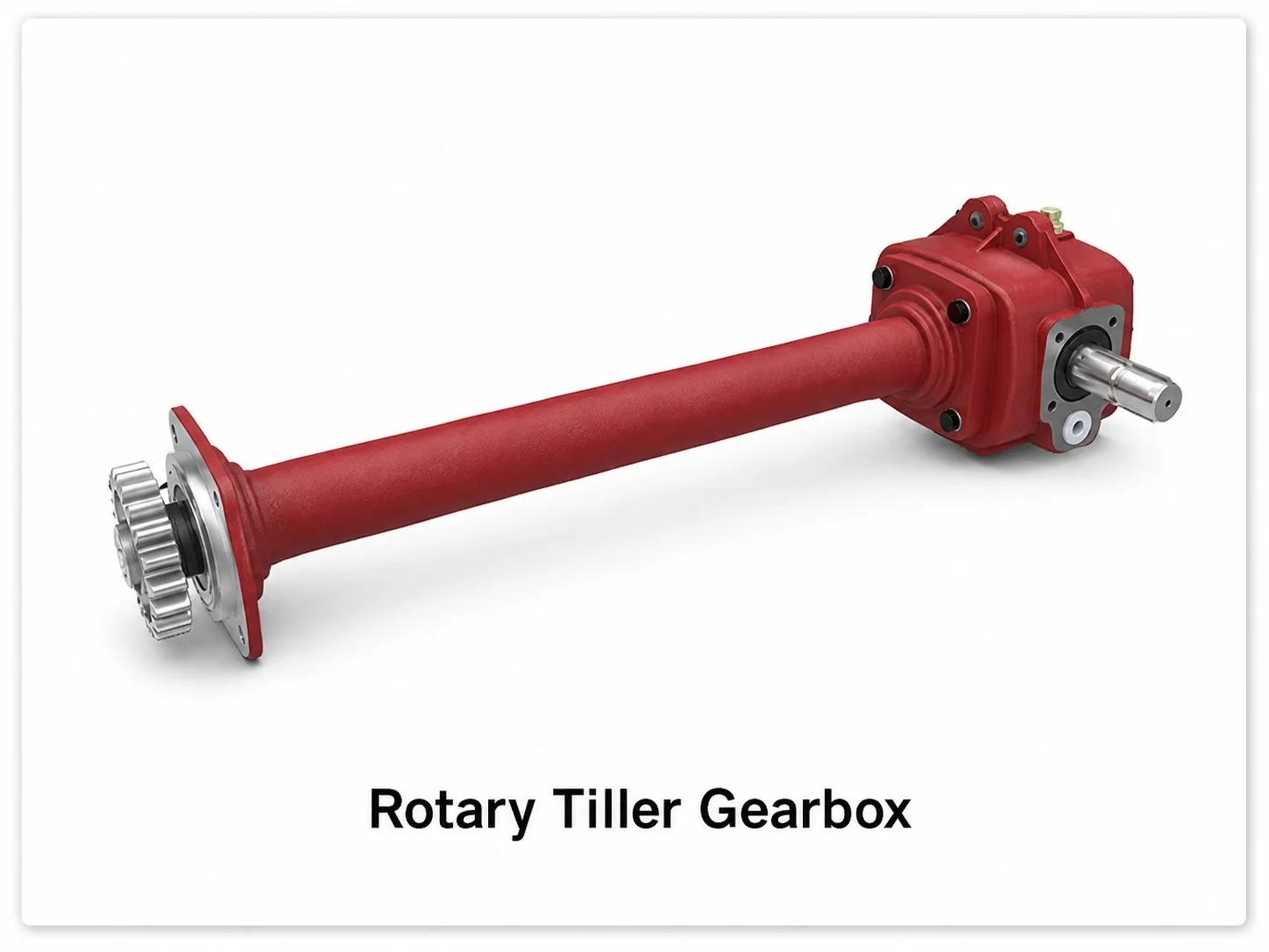
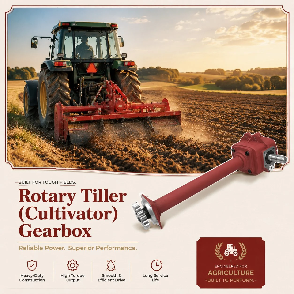
The fundamental difference between a spading machine and a rotary tiller is how the soil is moved. A rotary tiller uses forward-rotating blades that cut, shatter, and throw the soil — producing a fine, loose seedbed but destroying the soil aggregates, biological channels, and macropore structure that healthy soil depends on for water infiltration and root penetration. A spading machine lifts and inverts each clod intact, preserving the internal aggregate structure while achieving complete inversion of the tillage layer. This careful preservation of natural soil structure is the primary reason that spading machines are the preferred primary tillage implement for certified organic farming, regenerative agriculture, and high-value horticultural operations where soil health is a management priority. For comparison with conventional rotary tillage gearbox engineering, see our detailed guide on caja de engranajes del cultivador rotativo applications and design.
Reduction Gearbox Design for Crankshaft Drive
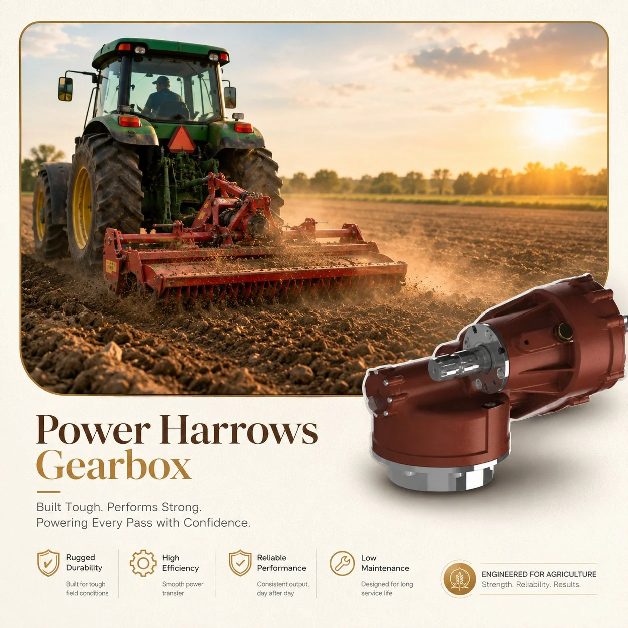
The gearbox architecture for a spading machine combines a right-angle bevel input stage (converting horizontal PTO rotation to the crankshaft orientation) with a parallel-shaft helical or spur reduction output stage that achieves the required total speed reduction. For ratios of 1:2.2 to 1:3.5, a single-stage bevel may suffice — but for the deeper-working, slower-cranking machines that require 1:4 to 1:5.4 reduction, a two-stage design (bevel input at 1:1.5 to 1:2, followed by a helical reduction at 1:2 to 1:2.7) distributes the total ratio across two gear meshes and keeps each stage within its efficient operating range. Manufacturers like Caja de engranajes de toma de fuerza Ever-Power offer both configurations, matched to the specific crankshaft speed and torque requirements of each spading machine model.
The output gear module for a spading machine gearbox is typically 5 to 8 mm — the same heavy-duty range used in deep cultivator gearboxes, reflecting the comparable torque levels transmitted at similarly low output speeds. The output shaft diameter at the crankshaft connection is 70 to 120 mm, sized to handle the combined torsional shear and bending loads imposed by the multi-throw crankshaft. Tapered roller bearings at the output position provide the combined radial and thrust load capacity needed for the cyclic loading pattern — each crankshaft revolution produces alternating thrust direction as the spade blades enter and exit the soil, creating a reversing axial load that deep-groove ball bearings cannot handle efficiently at the torque levels involved.
The crankshaft itself is not part of the gearbox (it is a separate forged or cast component that connects to the gearbox output flange), but the interface between the gearbox output and the crankshaft is a critical design feature. The connection must transmit the full output torque without relative movement (no fretting corrosion at the joint surfaces) while still allowing practical field disconnection for crankshaft replacement or spade blade service. Splined couplings with interference-fit hubs (hydraulically expanded for assembly and removal) provide the most robust connection, while keyed flanges offer simpler field service at the cost of lower torque capacity and a potential fretting site at the key-to-keyway contact.
Power-per-Metre Demand: Why Spading Requires Heavy Tractors
Spading machines consume 30 to 60 HP per metre of working width — the highest power demand of any primary tillage implement and substantially more than a rotary tiller (15 to 30 HP/m), a power harrow (12 to 25 HP/m), or a mouldboard plough (10 to 20 HP/m at equivalent depth). The elevated power demand directly reflects the fundamental mechanics of lifting rather than cutting: each spade blade must overcome the weight of the soil clod plus the adhesive and frictional forces that resist vertical extraction from the soil profile. A 2-metre spading machine therefore requires 60 to 120 PTO HP — demanding a medium to large tractor (100 to 180 engine HP) to provide adequate PTO power with reserve for the torque spikes that occur when the spades encounter compacted soil layers, root masses, or stones at the working depth.
The achievable forward speed of a spading machine is inherently limited by the crankshaft speed and the number of spade blades. At 150 RPM crankshaft speed with 8 blades per row, the machine processes 8 × 150 = 1,200 spade strokes per minute. Each stroke processes a soil slice approximately 100 to 150 mm wide (the blade width), so the machine advances 1,200 × 0.1 = 120 metres per minute at minimum blade spacing — approximately 7.2 km/h, which is well above the practical maximum forward speed of 2 to 3 km/h that soil quality considerations impose. In practice, the forward speed is limited not by the crankshaft capacity but by the requirement to produce overlapping spade strokes that leave no untilled strips between adjacent blade positions — a forward speed of 1.5 to 3 km/h at 100 to 200 RPM crankshaft speed achieves this continuous coverage across the full working width.
Organic Matter Incorporation and Cover Crop Management
The spading machine’s unique ability to bury surface material at full working depth without chopping it makes it the preferred implement for incorporating cover crops, green manures, crop residues, and applied compost into the soil profile. A rotary tiller chops and mixes surface material throughout the shallow tillage layer (150 to 200 mm), where it decomposes rapidly in the aerobic surface zone and contributes little to lasting soil organic matter. A spading machine buries the same material at 200 to 400 mm depth — below the zone of rapid aerobic decomposition — where it breaks down slowly under anaerobic conditions, contributing to stable humus formation and long-term soil carbon storage.
El caja de cambios agrícola driving the spading machine during cover crop incorporation experiences higher torque than during clean-field spading because the surface vegetation adds resistance to the spade entry — long-stemmed cover crops (rye, vetch, crimson clover at 0.5 to 1.5 metres height) wrap around the spade blades and increase the lifting force by 20 to 40 percent compared to bare-soil operation. The gearbox must be rated for this vegetation-loaded torque condition, not just the clean-soil figure — and the slip clutch on the PTO driveline must be calibrated high enough to allow the machine to process heavy cover crop residue without false-triggering, while still releasing before a genuine obstruction (large stone, buried metal) damages the crankshaft or gearbox.
Stone Handling and Overload Protection
Spading machines handle stones and buried obstacles more gently than rotary tillers because the spade blade lifts the stone rather than striking it with a high-velocity impact. A rotary tiller blade travelling at 5 to 7 m/s tip speed hits a stone with kinetic energy proportional to velocity squared — producing violent impacts that crack the stone, damage the blade, and transmit shock loads through the gearbox. A spading machine blade entering the soil at only 1 to 3 m/s vertical velocity contacts the stone at much lower energy, and the crankshaft mechanism simply lifts it with the surrounding soil clod rather than attempting to shatter it. This inherently gentler stone handling produces less blade wear, less gearbox shock loading, and less stone fragmentation (an advantage when the goal is to remove whole stones from the field rather than breaking them into smaller pieces that remain in the tillage layer).
However, immovable obstacles (bedrock outcrops, buried concrete, large tree roots) still generate overload conditions that require protection. The primary protection is a eje de la toma de fuerza slip clutch calibrated to release at 1.5 to 2.0 times the rated continuous torque — protecting the gearbox from the crankshaft stall condition that would occur if a spade blade encountered an obstacle it cannot lift. Individual spade blades on premium spading machines are also mounted on spring-loaded breakaway assemblies that allow each blade to deflect rearward when it encounters an immovable obstacle, then spring back to its working position once the obstacle passes — protecting both the blade and the crankshaft bearings from the concentrated impact loading that a rigid blade mount would transmit.
The gearbox housing material specification for spading machines follows the same logic as deep cultivators: ductile iron (EN-GJS-400-15 or higher grade) provides the impact toughness needed to survive the residual shock loading that passes through the slip clutch and breakaway mechanisms. Standard grey cast iron housings are inadequate for the cyclic shock environment of soil-engaging implements operating at 200 to 400 mm depth — the combination of sustained high torque and intermittent impact overload produces fatigue cracking in grey iron housings within 3 to 5 seasons, while ductile iron housings withstand the same loading for 10 to 15+ seasons. The weight penalty of ductile iron compared to grey iron is modest (approximately 10 percent heavier for the same geometry) and is far outweighed by the extended service life and the elimination of the catastrophic housing fracture risk that grey iron presents in this application.
Seasonal Maintenance and Bearing Inspection
Spading machines operate on a sharply seasonal basis — typically 50 to 200 hours per year concentrated in the spring or autumn primary soil preparation window. The intense cyclic loading during this period generates more cumulative bearing fatigue per hour of operation than most agricultural gearboxes because each crankshaft revolution produces a complete load reversal at every bearing position. Thorough pre-season maintenance should include a complete oil change with fresh synthetic PAO-based EP gear oil ISO VG 320 (one grade heavier than the VG 220 used in medium-load applications, providing the elevated viscosity needed for adequate film thickness at the high contact stresses of low-speed, high-torque gear mesh), bearing play verification (carefully rotate the crankshaft by hand to check for roughness or axial free-play that indicates bearing wear), and individual spade blade inspection for wear or damage that would increase the lifting force and overload the gearbox.
Post-season storage should include thorough cleaning of the gearbox exterior (soil left on the housing traps moisture and accelerates corrosion during the off-season), topping up the oil level to maximum (a completely full housing reduces the internal air volume available for condensation), and applying protective grease to the gearbox-to-crankshaft coupling interface to prevent fretting corrosion at the splined or keyed joint during the extended 8 to 10 month storage period. Inspect the gear backlash at each seasonal service — the high cyclic loading of spading produces substantially more gear tooth wear per operating hour than continuous-rotation applications, and backlash increasing to 0.50 mm or more at the output gear mesh indicates significant wear that warrants gear and bearing replacement before the next operating season.
Preguntas frecuentes
Tillage Innovation from the Ground Up
From shallow seedbed preparation to deep organic matter incorporation — our crankshaft-drive reduction gearboxes deliver the precise, sustained torque that reciprocating spading demands. Ductile iron housings, oversized gear modules, and matched tapered roller bearings included as standard on every spading-specification unit.
Editor: Cxm